Türkiye'nin Lider Motor Tedarikçisi - Turkey's Leader Motor Supplier


Out Of Stock
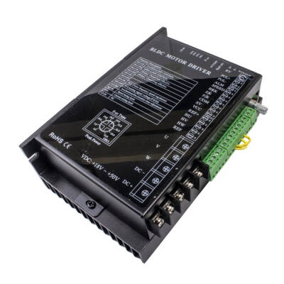
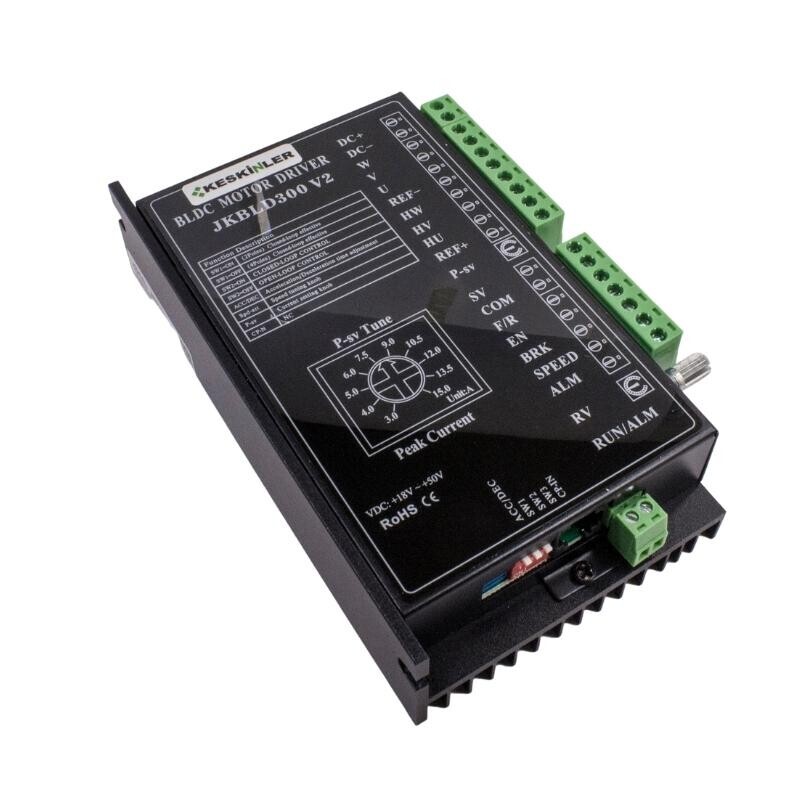
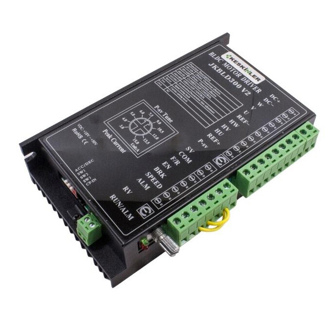
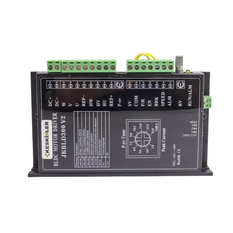
Notify me when its in stockThe JKBLD300 300W Brushless BLDC Motor Driver, Ingenium Drives, is a 300W Brushless DC Motor Driver capable of operating a 3-phase Brushless DC Motor with Hall Effect Sensors in closed-loop configuration.
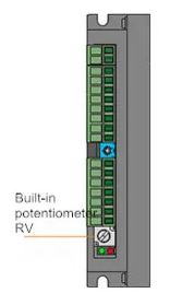
The 300W Brushless DC Motor Driver can be controlled in two ways: either with an external controller (such as PLC and SCM) that provides signals to the driver, or with the help of an internal potentiometer to control the BLDC Motor speed. At the same time, the driver has a large starting torque, fast start and brake, positive and negative switching, which is a combination of manual and automatic control.
Application areas are generally industrial machines and autonomous robots.
|
Driver Parameters |
Minimum Value |
Recommended Value |
Maximum Value |
Unit |
|
Output Current |
0 |
15 |
35 |
A |
|
Supply Voltage |
18 |
48 |
50 |
VDC |
|
Hall drive current |
- |
20 |
- |
mA |
|
Hall signal voltage |
4.5 |
5 |
5.5 |
V |
|
Applicable motor speed |
0 |
- |
20000 |
RPM |
|
Environmental Factors |
Environmental indexes |
|
To be avoided |
Dust, oil stains, and corrosive gas |
|
Operating Temperature Range |
10℃~+50℃ |
|
Humidity |
40-90%RH (no condensation) |
|
Vibration |
5.9m/s2 Max |
|
Storage Temperature Range |
-20℃~+125℃ |
|
Cooling |
|
|
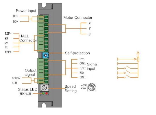
Signal |
Terminal |
Function |
|
Input |
SV |
1.External potentiometer; 2. Analog signal input; 3.PWM pulse width. |
|
COM |
Common connection point (0V reference level) |
|
|
F/R |
When the high-level input is applied, the motor rotates clockwise; when the low-level input is applied or F/R and COM are connected, the motor rotates counterclockwise. |
|
|
EN |
When the high-level input is applied, the motor stops slowly; when the low-level input is applied or EN and COM are connected, the motor runs. |
|
|
BRK |
When a high level is applied or the terminal is left floating, the motor brake stops; when a low level is applied or EN and BRK are connected, the motor runs. |
|
|
Output |
ALM |
The fault output signal of the motor or driver is 5V under normal conditions; when a fault occurs, the level is 0V. |
|
SPEED |
|
Turn the RV knobs clockwise until a "click" sound is heard; the motor starts to run. Turn the RV knobs clockwise to accelerate the motor. Turn the RV knobs counterclockwise to decrease the motor speed, and the motor will stop when a "click" sound is heard.
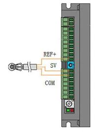
Use a suitable potentiometer with a resistance value of 10KΩ, connect the middle terminal to the SV terminal, and connect the other two terminals to the REF+ terminal and the COM terminal respectively.
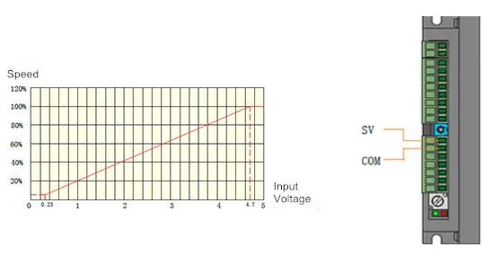
When the input voltage is 0.25V, the motor speed is 5% of the maximum speed; when the input voltage is about 4.7V, the motor speed reaches the maximum value.
Frequency: 1-3KHz Amplitude: 5V
Pulse width: Adjust the duty cycle for speed regulation.